Hey folks, if you’re working on high-frequency designs—think 5G, mmWave, radar, or even high-speed automotive ADAS—you already know that choosing the right PCB material is half the battle. And if you’re landed on Rogers PCB (we’re the folks who supply these, so trust us, we see this daily), there’s way more to nailing your design than just grabbing a sheet of RO4003 or RO4350. Let’s break down the real, hands-on considerations we walk every customer through, no fluff, no corporate jargon—just what actually messes up or makes your RF design work. Rogers PCB
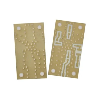
First off, let’s get one basic thing straight: Rogers materials aren’t your everyday FR-4. FR-4 is great for low-speed, low-cost boards, but when you’re pushing 1 GHz and above, FR-4 loses its mind with signal loss, dielectric constant variation, and thermal expansion. That’s why Rogers was built for RF: their laminates are made with woven glass reinforced hydrocarbons or PTFE, which are way more stable. But stability here isn’t a one-size-fits-all term—we’re talking temperature stability, frequency stability, even humidity stability. Let’s start with dielectric constant (Dk), because this is the foundation. If your Dk is off, your impedance will be garbage, no matter how good your trace layout is.
A lot of designers just grab the datasheet’s nominal Dk and go, but here’s the catch: Rogers Dk isn’t a static number. It changes with frequency and temperature. For example, RO4350B has a nominal Dk of 3.48 at 10 GHz, but if you run that at 28 GHz (common for 5G mmWave), it might shift a tiny bit—like 0.02 or 0.03. That’s not a big deal for low-frequency, but at 39 GHz, that 0.02 difference can throw your impedance off by 5 to 10 ohms, which is enough to cause signal reflections, lousy gain, or even link failure. And temperature? If your radar is running outside in 120°F desert heat vs. -40°F arctic cold, Dk can shift another 0.01 to 0.04. We always tell customers: don’t use room-temperature Dk values for your final calculations. Use the frequency and temperature range your product will actually operate in. That’s why we supply our customers with Dk vs. frequency curves right on the order form—no more guessing.
Next up: dissipation factor (Df), which is basically how much power your material eats up as heat. At high frequencies, Df is way more important than conductivity for signal loss. Rogers materials have way lower Df than FR-4—like 0.0037 for RO4350B vs. 0.02 for standard FR-4. But again, don’t just look at the nominal Df. Df also increases with frequency. For mmWave designs (24 GHz to 100 GHz), a 0.001 jump in Df is a big deal—you could lose 1 dB per inch of signal, which adds up fast in a small transceiver. We’ve had customers come to us after using a generic high-frequency material that claimed low Df, but when we tested it at their actual operating frequency, Df was twice the spec. So always ask for Df at your frequency, not just the datasheet’s test frequency. That’s a mistake we see all the time, and it’s avoidable.
Then there’s copper foil choice. Rogers laminates come with different copper types—rolled copper vs. electrodeposited (ED) copper. A lot of designers just pick the cheapest, but no. For RF, surface roughness of the copper is make-or-break. When signals are high-frequency, they don’t travel through the full thickness of the copper—they stay in the skin depth, which is like 1 to 2 microns at 10 GHz, even smaller at higher frequencies. If your copper’s surface is rough, that’s like adding extra length to your trace, and it increases conductor loss. Rolled copper has way smoother surface roughness (like 1 to 3 microns Ra) than standard ED copper (which can be 5 to 10 microns Ra). For 5G mid-band or automotive radar, ED copper might work, but for mmWave, you need rolled copper—otherwise, you’re losing 0.5 to 1 dB per inch of signal, which kills your range. We offer both, but we never push ED copper for high-frequency designs without making that tradeoff clear. Also, make sure the copper is bonded well to the laminate—bad lamination leads to delamination, especially if your board has thermal cycling. We do a pull test on every Rogers board we supply for critical RF apps to catch that.
Thermal management is another one people sleep on. RF circuits generate heat, especially power amplifiers (PAs) and LNAs, and Rogers materials have lower thermal conductivity than metal cores, but way better than FR-4. But if your board has a high-power component, you can’t just rely on the laminate to dissipate heat. A common mistake is putting a big PA right on a thin Rogers laminate without a thermal relief or a metal slug. We tell customers to use a thicker core laminate (like 0.062” instead of 0.020”) for high-power sections, or add a thermal pad with a thin dielectric layer between the PA and the copper. Also, take into account the coefficient of thermal expansion (CTE) mismatch. Copper has a CTE of ~17 ppm/°C, and Rogers laminates are around 15 ppm/°C for RO4350B—super close, way closer than FR-4’s 20 ppm/°C. That means less stress on the copper traces during thermal cycling, which reduces the chance of trace cracking or delamination. But if you’re mixing Rogers with another material, make sure the CTE is matched, or you’ll have issues. We work with customers on stackup designs that balance Dk, thickness, and thermal needs—no one size fits all here.
Impedance control is non-negotiable. RF signals are sensitive to trace width, dielectric thickness, and Dk—so your stackup has to be spot-on. For a microstrip line (the most common RF trace type, on top of a laminate with a ground plane), a 0.1 mm change in trace width can shift impedance by 5 ohms. That’s why when we supply Rogers boards, we give customers a trace calculator specific to their material grade—no generic calculators that use FR-4 Dk. Also, don’t forget about the ground plane. The ground plane has to be continuous under the RF trace, no gaps, because a gap will cause signal reflection. We see customers try to route a ground plane around a component, and leave a 0.5 mm gap, and they wonder why their signal is garbage. Rule of thumb: ground plane is like a mirror for RF signals—any break, and the signal bounces back. Also, for differential pairs (used in high-speed RF), the spacing between the two traces has to be consistent, and Dk has to be the same on both sides. We do impedance testing on every prototype we ship, so customers know their traces are within ±5% of their target impedance—no surprises.
Bend and twist—wait, no, mechanical design. Rogers laminates are rigid, but they’re not unbreakable, and they have different flexural strength depending on the grade. If you’re making a flexible RF board (like for a wearable or a folded antenna), RO4003C has better flexibility than RO4350B, but even then, you can’t bend it too tight. Bend radius should be at least 5 times the board thickness to avoid cracking the laminate or delaminating the copper. Also, avoid sharp corners in RF traces—sharp corners cause impedance discontinuities and signal reflection. Round your corners to at least 0.25 mm, especially for high-frequency traces. That’s a quick fix that makes a huge difference, and a lot of new designers miss it.
Humidity and environmental exposure. Rogers materials are pretty resistant to humidity, but if your product is going in a marine environment or a high-humidity industrial setting, you still need to consider it. Dk can shift a tiny bit if the laminate absorbs moisture, even though Rogers laminates absorb way less than FR-4 (less than 0.02% vs. 0.2% for FR-4). For extreme environments, we recommend coating the board with a conformal coating, like acrylic or parylene, which adds another layer of protection without affecting RF performance too much. Also, make sure your board is sealed properly, especially if it’s going outdoors—moisture getting into the board can cause short circuits, and even if it doesn’t affect your initial design, it will over time.
Wait, let’s talk about stackup design, because that’s where all these considerations come together. A bad stackup can turn a great material into a bad design. For a typical 4-layer RF Rogers board, you don’t want to route all your RF traces on the top layer with a ground plane only on layer 2—you need a reference plane every time. So stackup should go: top layer (RF traces), layer 2 (ground plane), layer 3 (power/control traces), layer 4 (ground plane or power). That way, RF traces have a solid ground reference, which reduces EMI and signal loss. If you have to route a trace on an inner layer, it should have a ground plane above and below it—like a stripline design, which is way more shielded than microstrip. Stripline is great for high-frequency, high-noise environments, because it’s less susceptible to interference. We help customers build stackups that match their frequency and power level—for example, a 28 GHz 5G transceiver might use a stripline for the main signal trace, while a lower-power sensor can use microstrip.
Now, a few common mistakes we see all the time, so you can avoid them. First, using the wrong material for the job. Someone tried to use RO4003 for a 77 GHz automotive radar last year, because it’s cheaper, but RO4003’s Df is a touch higher than RO4350B, and at 77 GHz, that added up to 2 dB loss per inch—their radar only worked half the range it should have. Second, ignoring skin effect. We mentioned earlier that signals stay in the skin depth, so don’t use copper that’s too thick. A lot of designers use 2 oz copper for RF traces, which is way thicker than needed, and the extra copper just adds weight and cost, no benefit. For high-frequency, 1 oz copper is more than enough—even 0.5 oz for mmWave. Third, not testing the actual material. We’ve had customers design a board based on a datasheet, but when they got the laminate, it was a different batch with a 0.05 Dk shift, and their impedance was off. So always get a sample of the actual material we supply, test it in your lab, before you do a full run. We can send free samples, by the way—just reach out if you need one.
At the end of the day, the goal with Rogers PCB for RF is to minimize signal loss, keep impedance consistent, and make sure the material behaves like the spec says it will in your actual operating conditions. Every design is different—whether you’re making a 5G base station, a weather radar, or a wearable antenna—so one-size-fits-all rules don’t work. That’s why we work with every customer one-on-one: we ask about their frequency range, power level, environment, and performance targets, then help them pick the right laminate, copper, stackup, and design tweaks to make it work. If you’re in the middle of an RF design and hitting snags, or you’re just starting out and want to make sure you don’t mess up the material choices, we’re here to help. We supply Rogers PCBs to all kinds of companies, from startups to big defense contractors, and we know the ins and outs of every grade.

So if you’re ready to get a quote, or you want to run through your design questions, just reach out. We don’t do hard sales—we do honest advice, because our customers’ success is our success. No fine print, no generic promises, just Rogers PCBs that work for your RF applications.
Single Layer FR4 PCB Board References:
- Rogers Corporation. (2022). High-Frequency PCB Material Design Guide. Rogers Corp.
- HyperLynx. (2021). RF Impedance Control and Material Selection for High-Frequency PCBs. Siemens EDA.
- Microwave Engineering Handbook. (2020). Dielectric Materials for RF and Microwave Applications. IEEE Press.
Fastline Circuits Co., Limited
Fastline Circuits Co., Limited is one of the most professional rogers PCB manufacturers and suppliers in China. With abundant experience, we warmly welcome you to wholesale durable rogers PCB made in China here and get quotation from our factory. All customized products are with high quality and competitive price.
Address: Room 301, Building B3, Fuqiao 4th District, Qiaotou Community, Fuhai Subdistrict, Bao’an District, Shenzhen, Guangdong Province, China
E-mail: sales@fastlinepcb.com
WebSite: https://www.fastlinepcb.net/
